
 English


Views: 0 Author: Site Editor Publish Time: 2026-09-26 Origin: Site


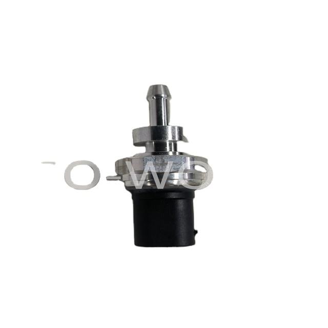
Moisture in exhaust gases is an unavoidable byproduct of internal combustion. Every time an engine runs a cold start or a short drive cycle, high-temperature exhaust vapor rapidly cools and condenses inside the piping. This liquid accumulation leads directly to component failure through internal corrosion, electrical shorting, or physical damage from ice expansion inside the housing. When these parts fail, you get false Diesel Particulate Filter (DPF) or Gasoline Particulate Filter (GPF) regeneration triggers. The engine derates, forces the vehicle into limp mode, and causes unplanned commercial downtime. Often called Exhaust Back Pressure (EBP) sensors or Exhaust Gas & Differential Pressure Sensors (EDPS), these parts keep modern emission systems running. Protecting them takes a multi-layered approach. You have to look at physical routing, internal engineering, and strict procurement standards to keep trucks and equipment out of the shop.
Orientation is Critical: Mechanical installation (e.g., mounting the sensor with the pressure port pointing downward) is the primary defense against moisture pooling.
Tubing and Routing Matter: Engineered pressure lines must utilize continuous downward slopes or specific condensation loops to prevent water vapor from reaching the sensor diaphragm.
Internal Engineering Varies: High-quality sensors utilize conformal coatings, isolated diaphragms, and specialized seals to resist moisture that bypasses mechanical defenses.
Supplier Selection Impacts Longevity: Vetting an exhaust pressure sensor supplier requires analyzing their specific mitigation designs for cold-weather and high-moisture environments.
Exhaust gases leave the combustion chamber at extremely high temperatures, often exceeding 600°C under load. At these temperatures, the gas carries significant volumes of water vapor. As this gas travels through cooler pressure lines toward the monitoring components, thermal dynamics shift rapidly. The temperature of the gas drops below its dew point. High-temperature vapor immediately condenses into liquid water upon contacting the cold metal walls of the pressure tubing. This phase change is the root cause of moisture accumulation in emission monitoring systems.
Environmental factors heavily influence this condensation process. Low ambient temperatures and high external humidity accelerate the cooling rate of the pressure lines. Winter operations in freezing climates create a massive temperature delta between the hot exhaust gas and the freezing steel pipes. Operational profiles also play a major role in moisture retention. Frequent short trips prevent the exhaust system from reaching optimal operating temperatures. When the system runs cold, moisture never fully evaporates. It remains trapped within the lines, building up over successive drive cycles until it forms a solid column of water.
Modified exhaust systems alter thermal dynamics further. Catless setups, larger diameter piping, or aftermarket turbos change backpressure characteristics and heat retention. These modifications often exacerbate condensation buildup compared to factory configurations. The absence of catalytic converters removes a major heat source, allowing gases to cool much faster in the downstream piping. This rapid cooling forces more water vapor to condense before it exits the tailpipe, pushing excess moisture straight up the pressure lines.
When liquid water reaches the internal components, failure is imminent. Freezing presents the most immediate physical threat in cold climates. Water expands by approximately nine percent as it turns to ice. This mechanical stress pushes directly against the sensitive internal sensing diaphragm. The expansion causes permanent calibration shifts, skewed voltage outputs, or outright rupture of the ceramic element. Once the ceramic cracks, the unit is permanently dead.
Corrosion acts as a silent, progressive destroyer. Exhaust condensation is not pure water; it is highly acidic. It mixes with sulfur dioxide and nitrogen oxides from the combustion process to form sulfuric and nitric acids. This acidic mixture attacks terminals, solder joints, and internal circuitry. It eats through protective layers, destroys electrical continuity, and creates internal shorts that the Engine Control Unit (ECU) registers as open circuits. You will often see green or white powdery buildup on the connector pins when this happens.
Signal degradation occurs even without physical destruction. Water droplets block the narrow pressure port leading to the diaphragm. These droplets act as a hydraulic damper against the incoming pressure signal. The ECU receives sluggish response times and erratic readings. This dampening effect triggers diagnostic trouble codes, delays necessary particulate filter regenerations, and severely impacts engine performance. The engine computer thinks the DPF is clogged because the water column is artificially inflating the pressure reading.
Failure Mode | Mechanism of Action | ECU Diagnostic Symptom | Physical Evidence |
|---|---|---|---|
Freezing | Ice expansion ruptures internal diaphragm | Permanent out-of-range high/low voltage codes | Cracked housing or shattered internal ceramic |
Corrosion | Acidic moisture destroys electrical traces | Intermittent signal loss, open circuit codes | Green/white oxidation on connector pins |
Signal Dampening | Water droplets block pressure port | Sluggish response, delayed DPF regeneration | Liquid water dripping from the port upon removal |
Soot Sludge | Water mixes with carbon soot to form blockages | Stuck pressure readings, no variance under load | Thick black paste clogging the pressure tube |
Mechanical installation dictates survival. The industry-standard rule is vertical mounting, universally known as the "nipple down" orientation. Gravity acts as the primary defense mechanism against moisture. When the pressure port points directly downward, any condensation that forms inside the housing naturally drains back down the line. It returns to the main exhaust pipe, keeping the diaphragm dry. You cannot rely on internal seals alone; you must let gravity do the heavy lifting.
Technicians logging Exhaust Manifold Pressure (EMAP) or installing aftermarket turbo kits must fabricate custom brackets. These brackets must strictly maintain this downward-pointing orientation. Sideways or upward mounting guarantees that moisture will pool against the diaphragm. Even a slight upward angle allows condensation to collect over time, eventually submerging the sensing element. We see this constantly in custom builds where mechanics prioritize a clean engine bay look over functional fluid dynamics.
Inspect existing brackets and mounts regularly during routine maintenance. Engine vibration bends thin metal brackets over thousands of miles. A unit that started perfectly vertical may tilt due to metal fatigue or loose fasteners. Ensure vibration hasn't altered the intended drainage angle. Reinforce flimsy brackets with thicker gauge steel to maintain structural rigidity under heavy engine loads. If you can bend the bracket with your bare hands, it will not survive a year on a commercial diesel engine.
Pressure tube routing requires precise engineering. A continuous downward gradient from the unit to the exhaust pipe tap is mandatory. Any dip, sag, or horizontal run in the line creates a trap where water accumulates. Installers must route hard lines and flexible hoses to ensure a steep, uninterrupted path back to the exhaust stream. If you use flexible silicone hoses, secure them with P-clamps every few inches to prevent sagging.
Some systems utilize mechanical condensation traps, pigtail coils, or expansion chambers. These components deliberately cool the gas and capture moisture before it ascends to the sensitive electronics. The trapped water sits in a designated low point. It then evaporates safely when exhaust temperatures finally rise during a highway drive or active regeneration cycle. These loops act as a buffer zone, sacrificing a small section of tubing to protect the expensive electronics above.
Avoid drilling "weep holes" in exhaust systems. This controversial practice is a flawed, non-compliant workaround. It introduces exhaust leaks and skews the precise pressure readings required by the ECU. Weep holes often spray acidic condensation onto adjacent components like oxygen sensors, wiring harnesses, and drivetrain parts. They ruin the pressure delta and create secondary component failures. Fix the routing geometry instead of drilling holes in the pipe.
Disconnect the pressure line from the sensor housing.
Trace the line down to the exhaust pipe, checking for any horizontal runs or sagging sections.
Apply compressed air to the top of the line and blow any accumulated soot or water back into the exhaust stream.
Install rigid P-clamps to support any flexible hoses, ensuring a minimum 15-degree downward slope.
Reconnect the line and verify the mounting bracket holds the unit perfectly vertical.
Modern engineering isolates the piezoresistive sensing element from harsh exhaust media. Engineers use protective fluorosilicone gels, stainless steel diaphragms, or robust ceramic elements. These materials resist acidic moisture and prevent direct contact with delicate internal circuitry. The physical barrier ensures that even if condensation reaches the chamber, it cannot short the electrical pathways. The gel acts as a flexible shield, transmitting the pressure wave while blocking the liquid.
Internal O-rings and specialized weather-pack electrical connectors block moisture ingress from the external environment. A robust seal prevents ambient humidity, road spray, or engine bay wash-down water from entering the housing. If the external seal fails, water wicks down the wiring harness directly into the pins. You must ensure the connector clicks firmly into place and the silicone weather seal is intact.
A highly engineered Exhaust Pressure Sensor relies on these internal barriers when mechanical drainage falls short. High-tier components utilize conformal coatings on the printed circuit board. This coating acts as a final line of defense, repelling acidic moisture that manages to bypass the primary diaphragm isolation. Without this coating, a single drop of acidic water will bridge the solder joints and fry the board instantly.
A differential exhaust pressure sensor faces unique vulnerabilities. It utilizes two ports, measuring pressure upstream and downstream of the particulate filter. This exposes the unit to two separate condensation pathways. If moisture blocks either port, the ECU calculates an incorrect pressure delta, leading to improper filter regeneration. The system relies on the exact difference between these two ports to determine soot load.
Originally exclusive to diesel engines, these dual-port units now appear heavily in modern petrol engines equipped with GPFs. This broadens the need for robust condensation protection across all fuel types. Petrol exhaust gases contain high levels of water vapor, making GPF systems highly susceptible to cold-weather freezing. You will often see these fail on delivery vehicles that do constant stop-and-go driving without ever reaching highway speeds.
Internal baffling and dual-chamber isolation protect the differential circuitry. These designs prevent cross-contamination between the high-pressure and low-pressure sides. They stop moisture from pooling across the internal bridge. Advanced designs incorporate micro-drainage channels within the plastic housing to route condensation away from the sensing elements. This ensures that even if water enters the high-pressure port, it cannot bleed over and corrupt the low-pressure reading.
Technicians often find drops of water under the housing during inspections. Proper diagnostic triage determines the root cause. You must differentiate between harmless external condensation and a critical internal seal failure. External condensation forms on the cold plastic housing during rapid temperature shifts in the engine bay. It is entirely harmless, sits purely on the surface, and evaporates quickly once the engine bay heats up.
An internal seal failure actively leaks exhaust moisture through the housing itself. To test this, wipe the plastic completely dry with a shop towel. Run the engine under load and monitor the component. If water pushes out from the electrical connector pins or the ultrasonic weld seam of the housing, the internal seal has ruptured. Replacement is mandatory to prevent wiring harness damage. Do not try to seal it with silicone; the internal board is already compromised.
Check the pressure lines for blockages before installing a new part. Disconnect the lines from the housing and blow compressed air through them toward the exhaust pipe. If a large volume of water or thick soot ejects from the line, the routing geometry is flawed. Address the sagging line before installing a replacement. If you skip this step, the new part will fail exactly like the old one within a few weeks.
European diesel applications present distinct routing challenges due to compact engine designs. The Renault DPF exhaust pressure sensor configuration requires specific mounting strategies to survive cold-weather climates. Factory routing often navigates tight spaces near the firewall, increasing the risk of horizontal line runs where water can pool. Mechanics working on these chassis know how difficult it is to maintain a proper downward slope.
Common failure points involve rigid metal lines that transfer heat too quickly, causing rapid condensation. Updated bracket designs and insulated lines mitigate this issue. Thermal insulation keeps the exhaust gas above its dew point longer, reducing liquid water formation before it reaches the port. Upgraded replacement kits often include these thermal sleeves. Always install the thermal sleeve; leaving it off guarantees premature failure during the winter months.
PSA group engines manage backpressure monitoring in extremely cramped engine bays. The Peugeot exhaust pressure sensor setup faces geometric constraints that make ideal line routing difficult. The DPF is often mounted close to the block, requiring sharp bends in the pressure tubing. These sharp bends act as natural choke points where soot and water mix into a thick sludge.
Engineers face trade-offs between accessibility for maintenance and optimal vertical mounting. OEM updates have addressed moisture pooling by redesigning the DPF housing tap angles. This ensures the initial pressure takeoff points downward, utilizing gravity immediately at the source. Technicians must ensure aftermarket replacement pipes match these updated tap angles exactly. If you weld in a generic bung at a 90-degree angle, you will trap water immediately.
Evaluating aftermarket versus OEM parts requires a strict framework based on verifiable engineering data. Look at operating temperature ranges and Ingress Protection (IP) ratings of the connector. IP67 or IP69K ratings ensure the external housing withstands severe moisture, high-pressure washing, and ambient humidity. If the spec sheet does not list an IP rating, do not buy it for a commercial fleet vehicle.
Diaphragm material specifications matter significantly. Verify whether the internal element uses standard silicon or upgraded ceramic and stainless steel components designed for acidic environments. Units built with inferior plastics will warp under under-hood temperatures, compromising the internal weather seal and allowing condensation to breach the circuitry. You get what you pay for when it comes to high-temperature plastics.
Component Feature | Low-Tier Aftermarket | High-Tier / OEM Grade |
|---|---|---|
Diaphragm Material | Bare Silicon | Fluorosilicone Gel / Ceramic |
PCB Protection | None | Conformal Coating |
Housing Assembly | Glued Seams | Ultrasonic Welding |
Connector Rating | IP65 (Splash proof) | IP69K (High-pressure wash proof) |
Fleet managers and technicians must ask an exhaust pressure sensor supplier tough questions. Demand data on testing protocols for thermal shock, moisture resistance, and exact-fit bracket geometry. A reliable manufacturer tests their components against rapid freeze-thaw cycles to simulate harsh winter operations. They should be able to provide documentation showing how their parts handle -40°C to 125°C temperature swings.
Comprehensive warranties must account for environmental failures. Baseline electrical defects are easy to cover. A reliable manufacturer stands behind their product when facing internal freezing or seal degradation caused by condensation. Ensure they provide clear documentation on their internal potting compounds and isolation techniques. If they blame every failure on "water damage" without acknowledging their own seal integrity, find another source.
Audit your current fleet's mounting orientations to ensure all pressure ports point strictly downward to utilize gravity drainage.
Clear out existing pressure lines using compressed air while completely disconnected from the electronics to remove trapped moisture and soot sludge.
Replace sagging flexible hoses with rigid lines or properly supported tubing to maintain a continuous downward gradient back to the exhaust pipe.
Inspect mounting brackets for vibration fatigue and reinforce them with thicker gauge steel to prevent the drainage angle from altering over time.
Consult with a vetted manufacturer to source high-durability replacements featuring isolated ceramic diaphragms and IP69K-rated connectors.
A: Water drops under the unit typically indicate either a failed internal seal allowing acidic exhaust condensation to escape, or external water pooling due to a compromised weather-pack connector. Immediate inspection is required to prevent electrical shorting and wiring harness damage.
A: While pressure lines can be blown out with compressed air, the unit itself is highly sensitive. Forcing air or solvent into the port will likely destroy the internal diaphragm. If moisture has breached the internal chamber, replacement is the only reliable fix.
A: Yes. Removing catalytic converters or altering pipe diameters changes thermal dynamics. Exhaust gases cool faster in modified systems, dropping below the dew point earlier and increasing liquid moisture buildup in the pressure lines.
A: Water expands by roughly nine percent when it freezes. If condensation pools inside the port and freezes overnight, this expansion exerts massive mechanical force against the internal sensing diaphragm, causing permanent calibration shifts or rupture.
A: No. Drilling weep holes introduces exhaust leaks and alters the precise pressure readings required by the ECU. It also sprays acidic condensation onto surrounding wiring and components, creating secondary failures.
A: The industry standard is vertical mounting with the pressure port pointing straight down. This orientation utilizes gravity to ensure any condensation drains back into the exhaust pipe rather than pooling against the internal electronics.


