
 English


Views: 0 Author: Site Editor Publish Time: 2026-09-30 Origin: Site


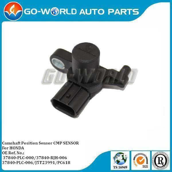
Engine misfires, erratic idling, or a sudden no-start condition frequently trace back to a breakdown in communication between engine sensors and the engine control unit (ECU). Modern internal combustion engines rely on absolute precision for fuel delivery and spark timing. When the ECU loses accurate angular data from the valvetrain, it cannot sequence cylinder firing. This leads to immediate performance degradation, poor fuel economy, or catastrophic timing failures. Resolving these issues requires understanding exactly what data the Camshaft Position Sensor transmits. You must know how the ECU interprets this signal under heavy engine loads. Finally, you need the technical criteria required to evaluate and source a reliable replacement component to restore factory performance. Without accurate sensor data, your diagnostic efforts will waste time and money on unnecessary parts.
Primary Function: The camshaft position sensor (CMP) provides the ECU with real-time data on the camshaft's exact rotational speed (RPM) and angular position, enabling precise cylinder identification.
Data Correlation: The ECU continuously cross-references CMP data with crankshaft position sensor data to synchronize fuel injection, ignition timing, and Variable Valve Timing (VVT) adjustments.
Diagnostic Reality: Sensor failures often present as signal degradation rather than immediate total failure, requiring scan tool live data and oscilloscope verification before parts replacement.
Sourcing Criteria: Selecting a replacement requires evaluating the camshaft position sensor manufacturer for strict adherence to OEM magnetic tolerances and thermal resistance standards to prevent premature failure.
The sensor continuously reads a reluctor wheel attached directly to the camshaft. This wheel, often called a tone ring, features a specific pattern of machined teeth and gaps. As the camshaft rotates, these metal teeth pass through the sensor's magnetic field. This physical movement alters the magnetic field, generating an electrical signal. The ECU monitors this signal to determine the exact angular position of the valvetrain at any given millisecond. The physical design of the tone ring varies by manufacturer, with some using a single notch and others using complex multi-tooth patterns to provide higher resolution data.
The ECU calculates the camshaft's rotational speed by measuring the frequency of these signal pulses. This data serves as a critical backup and reference point to the crankshaft sensor. In a four-stroke engine, the crankshaft rotates twice for every single rotation of the camshaft. The crankshaft sensor knows a piston is at Top Dead Center (TDC), but it cannot tell if that cylinder is on the compression stroke or the exhaust stroke. The camshaft data provides this missing context. By combining both inputs, the ECU knows exactly which cylinder is ready for combustion and seals the valves accordingly.
Modern engines utilize sequential fuel injection to maximize efficiency and power. This means the ECU fires each fuel injector individually, right before the intake valve opens. The ECU relies entirely on CMP data to trigger these injectors in the exact firing order. Without this angular data, the ECU loses its place in the combustion cycle. It cannot determine when to open the injector nozzle, leading to fuel pooling in the intake manifold or spraying against a closed valve.
This data relationship also dictates the ignition coil firing sequence. Coil-on-plug systems require precise timing to ignite the compressed air-fuel mixture at the optimal moment. Accurate camshaft position data prevents wasted spark events, where the coil fires on the exhaust stroke. It also eliminates the risk of pre-ignition or detonation, which can cause severe internal engine damage like cracked pistons or bent rods. The ECU uses the sensor's input to advance or retard ignition timing dynamically based on engine load, throttle position, and RPM.
Engines equipped with Variable Valve Timing (VVT) rely heavily on accurate camshaft data. VVT systems dynamically adjust the camshaft phase to optimize valve overlap across different RPM ranges. The ECU commands oil control valves to direct pressurized engine oil into the camshaft phasers. This hydraulic pressure physically rotates the camshaft independently of the timing chain sprocket to advance or retard the valve timing. However, the ECU needs physical confirmation that this mechanical adjustment actually occurred.
The CMP acts as the primary feedback mechanism in this closed-loop system. After commanding a timing change, the ECU monitors the sensor's signal to verify the new camshaft angle. If the sensor reports an angle that differs from the commanded target, the ECU detects a fault and logs a code. This feedback loop ensures the engine maintains optimal volumetric efficiency, emissions control, and power output under varying loads. Without this feedback, the ECU will disable the VVT system entirely to prevent piston-to-valve contact.
The mechanical relationship between the upper and lower engine dictates sensor integration. A timing chain or belt connects the crankshaft to the camshaft, forcing the cam to rotate at exactly half the speed of the crank. The crankshaft sensor monitors overall engine speed and precise piston position. It tracks the heavy rotational mass of the bottom end, providing a high-resolution signal of the crankshaft's exact degree of rotation.
Meanwhile, the camshaft sensor dictates the specific valvetrain phase. The ECU requires both signals to establish engine synchronization. The crank signal provides the baseline rhythm, while the cam signal provides the specific melody. If the ECU only had crank data, it would fire fuel and spark blindly on both compression and exhaust strokes. This dual-sensor architecture guarantees the ECU applies fuel and spark only when mechanically appropriate. When the timing chain stretches over thousands of miles, the physical relationship between these two sensors shifts, forcing the ECU to adapt its timing calculations.
When the ECU detects a mismatch between the cam and crank signals, it logs Diagnostic Trouble Codes (DTCs). Code P0340 typically indicates a circuit malfunction, meaning the ECU lost the electrical signal entirely due to a dead sensor or broken wire. Code P0011 points to a performance or timing over-advanced issue. This often means the signal is present, but it arrives at the wrong time relative to the crankshaft, usually pointing to a mechanical timing issue or a stuck VVT phaser.
Upon losing synchronization, the ECU initiates a limp-home mode protocol to protect the engine. Responses vary by manufacturer. Many ECUs revert to batch-fire injection, firing multiple injectors simultaneously rather than sequentially. This keeps the engine running but destroys fuel economy and idle quality. Other systems disable VVT entirely, locking the phasers in a default base position. In severe cases, the ECU cuts fuel pump operation entirely, resulting in a crank-no-start condition to prevent mechanical damage from out-of-phase combustion.
Signal loss translates directly to real-world drivability issues. Extended cranking is the most common early symptom. The ECU takes longer to guess the correct firing order without cam data, leading to hard starts. You will often experience rough idling and engine vibrations as the ECU struggles to balance cylinder contribution without precise timing data.
Stalling at operating temperature frequently occurs. Heat increases electrical resistance within a failing sensor. As the engine bay reaches maximum temperature, the internal circuit board expands, causing micro-cracks to separate and the signal to drop out completely. You will also notice sudden drops in fuel economy. When the ECU defaults to batch-fire injection or disables VVT control, the engine loses its volumetric efficiency. It burns more fuel to maintain the same power output, resulting in a noticeable drop in miles per gallon.
Automakers primarily use two types of sensors. Understanding their differences dictates how you test them in the bay.
Feature | Hall Effect Sensor | Magnetic Reluctance (VR) Sensor |
|---|---|---|
Wiring Configuration | 3-wire (Power, Ground, Signal) | 2-wire (Signal Positive, Signal Negative) |
Signal Output Type | Digital Square Wave (0V to 5V/12V) | Analog AC Sine Wave |
Voltage Generation | Requires external 5V or 12V reference | Generates its own AC voltage via induction |
Low RPM Accuracy | Excellent (reads accurately down to 0 RPM) | Poor (requires rotational speed to generate voltage) |
Common Failure Mode | Thermal breakdown of internal microchip | Internal coil winding shorts or opens due to vibration |
The ECU processes these signals differently. It reads the crisp on/off digital transitions of a Hall Effect sensor directly. For VR sensors, the ECU must convert the analog AC voltage into a digital signal using an internal analog-to-digital converter. Hall Effect sensors often fail due to thermal breakdown of their internal circuitry. VR sensors typically fail when engine vibration breaks the fine copper wire windings inside the housing, creating an open circuit.
Start your diagnostic process with scan tool live data. Navigate to the engine data stream and locate the Cam/Crank Sync state PID. This should read "YES" or "IN SYNC" while the engine runs. Monitor the Camshaft RPM PID. Look for immediate dropouts, freezing numbers, or erratic readings that do not match actual engine speed. If the scan tool shows 0 RPM while the engine is cranking, the ECU is blind.
For definitive proof of electrical failure, you must use a lab scope. Follow these steps to capture the waveform:
Identify the signal wire using a factory wiring diagram.
Back-probe the signal wire at the sensor connector using a fine-tipped probe. Do not pierce the wire insulation.
Connect the scope ground lead to a clean chassis ground or the battery negative terminal.
Set your time base to 20ms and your voltage scale appropriately (5V for Hall Effect, 10V for VR).
Start the engine and observe the pattern. A healthy Hall Effect waveform shows sharp, vertical 90-degree edges. A failing waveform presents rounded edges, signal dropouts, or erratic amplitude.
Misdiagnosis remains a massive risk in this area. Several mechanical issues mimic a failed sensor to the ECU. A stretched timing chain alters the physical relationship between the cam and crank. The sensor reads accurately, but the ECU flags a code because the timing is mechanically out of phase. Do not blindly replace the sensor for a P0011 code without checking chain slack or tensioner extension.
Damaged reluctor wheels also cause false flags. A bent or missing tooth on the tone ring disrupts the magnetic field, creating a dropout in the waveform. The sensor is fine; the trigger wheel is broken. You can often inspect the tone ring by removing the sensor and looking through the mounting hole with a borescope while turning the engine by hand. Finally, inspect the wiring harness. Chafed wires shorting to ground or broken internal copper strands will kill the signal before it reaches the ECU. Always verify power and ground at the connector before condemning the component.
Selecting a replacement dictates the long-term reliability of the repair. You must evaluate the camshaft position sensor manufacturer based on specific engineering criteria. Thermal stability is paramount. The sensor lives in a hostile environment, subjected to extreme engine bay heat cycling. High-quality manufacturers use advanced thermal epoxies to pot the internal circuit boards, preventing micro-cracks during rapid temperature changes.
Precise magnetic field strength is non-negotiable. The internal magnet must match OEM gauss ratings exactly. If the magnet is too weak, the sensor drops signals at high RPM. If it is too strong, it picks up electromagnetic interference (EMI) from the ignition coils or alternator. Furthermore, demand OEM-grade connector sealing. Weather-pack seals must keep moisture and engine oil out of the electrical pins. Avoid ultra-low-cost aftermarket sensors. They frequently utilize inferior magnets and cheap plastics, leading to immediate sync codes right out of the box.
Different engine architectures demand specific sensor tolerances. A universal approach fails in modern diagnostics. You must match the sensor to the specific demands of the engine control system.
Honda camshaft position sensor: Honda's i-VTEC systems demand highly responsive sensors. The ECU switches aggressive cam profiles in milliseconds based on oil pressure and RPM. The sensor must poll data at exceptionally high rates without signal degradation. Inferior sensors cause VTEC engagement delays, system lockouts, or harsh transitions between cam profiles.
Chevrolet camshaft position sensor: GM LS and LT engines utilize various configurations depending on the generation. Rear-mounted sensors sit near the firewall, suffering from severe heat soak and restricted airflow. Front-cover mounted sensors face timing chain debris and oil aeration. Replacements require robust housing materials to survive these specific environmental stressors without cracking.
Nissan camshaft position sensor: Nissan VQ engines are notoriously sensitive to aftermarket electronics. The ECU requires an exact OEM waveform match. Minor deviations in the square wave duty cycle will cause random stalling at stoplights, extended cranking, and immediate P0340 codes. Precision manufacturing is mandatory to keep these engines running smoothly.
Physical installation requires attention to detail. A sloppy installation will ruin a brand new sensor immediately. Follow these mechanical best practices to ensure a reliable repair:
Inspect the mounting bore for corrosion, carbon buildup, or old O-ring debris. Clean the surface thoroughly with a Scotch-Brite pad to ensure the sensor seats perfectly flat.
Check the air gap. An angled sensor alters the critical distance between the sensor tip and the reluctor wheel. If the air gap is too large, the magnetic field cannot reach the tone ring, resulting in a weak or missing signal.
Inspect the old sensor's magnetic tip. If you find heavy metallic debris or metal shavings attached to the magnet, you have internal engine wear. The timing chain or guides may be disintegrating.
Lubricate the new O-ring with clean engine oil to prevent tearing during insertion. A torn O-ring creates a massive vacuum leak or oil leak.
Torque the retaining bolt to factory specifications. Over-tightening distorts the plastic housing and cracks the internal circuit board.
Simply bolting on the new part is rarely sufficient. The ECU adapts to the wear and tolerances of the old sensor over time. It stores these timing variances in its non-volatile memory. Disconnecting the battery does not clear this specific data on modern vehicles. You must clear the existing DTCs using a capable scan tool.
Next, you must perform a Cam/Crank Relearn or Crankshaft Position System Variation Learn procedure. Using a bidirectional scan tool, initiate the relearn sequence. This usually involves bringing the engine to operating temperature, applying the parking brake, holding the brake pedal, and revving the engine to a specific RPM until the ECU cuts the fuel. This process recalibrates the ECU's timing baseline, syncing it perfectly to the precise manufacturing tolerances of the new sensor. Skipping this step often results in phantom misfire codes.
Connect a lab scope to the signal wire to verify waveform integrity and rule out false flags before condemning the sensor.
Inspect the engine wiring harness, connector pins, and the physical condition of the reluctor wheel for mechanical damage.
Source a replacement sensor that matches OEM magnetic tolerances and utilizes high-grade thermal epoxies to survive engine bay heat.
Perform a cam/crank correlation relearn procedure using a bidirectional scan tool immediately after installation to sync the ECU.
A: The engine may stall immediately, enter limp mode, or experience severe power loss. The ECU loses injection timing data, forcing it to guess the timing, revert to inefficient batch-fire injection, or cut fuel delivery entirely to prevent mechanical damage.
A: It depends on the manufacturer. Some ECUs will guess the timing based on the crankshaft sensor, resulting in long cranking times and poor performance. Other systems will disable the fuel pump and ignition coils, refusing to start the engine entirely.
A: The sensor itself is a plug-and-play hardware component and is not programmed. However, the ECU often requires a cam/crank correlation relearn procedure via a bidirectional scan tool to synchronize with the new sensor's precise manufacturing tolerances.
A: You can verify the signal by viewing live data parameters like Cam RPM or Sync Status on a bidirectional scan tool. For definitive proof, back-probe the sensor's signal wire with an oscilloscope to visually confirm a clean, uninterrupted waveform.
A: Common causes include installing a cheap aftermarket sensor with an incorrect waveform, a mechanically stretched timing chain, a damaged wiring harness, or failing to perform the required ECU relearn procedure after installation.


